Tuesday, December 28, 2021

DIY Kit Infrared Remote Control LED Light | ICStation

Today, I want to show you how to install and assemble DIY infrared remote control LED kit from ICStation. Press the switch button or any infrared remote controller on PCB to turn ON or OFF the lamp. For your information, this video is not sponsored. 


Installation

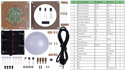
  1. Unboxing packaging DIY Kit Infrared Remote Control from ICStations. Below are the components lists.
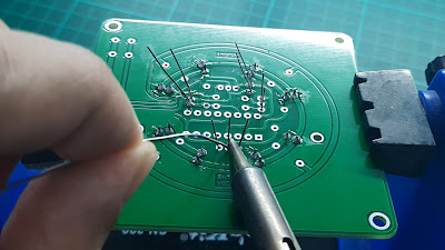
  2. Install 8 LEDs at L1-L8. Note: the longer pins are positive, and the short pins are negative. Insert the longer pin into the inner ring pad and the short pin into the outer ring pad.
  3. Solder the LEDs and cut any excess length of pins.
  4. Install S9015 and S8050 transistors at Q1, 100uF, and 10uF electrolytic capacitors at C1 and C2. Then, install a 1uF ceramic capacitor at C3.


  5. Solder the transistors and capacitors and cut any excess length of pins.
  6. Install IC CD4017 in U6 and solder it. Note: make sure to follow IC footprint marks on PCB.
  7. Install VS1738 IR receiver at U2. Solder and cut any excess length of pins.
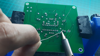
  8. Install the 470Ω resistor at R5-R8, 1kΩ resistor at R2 and R4, 10kΩ and 15kΩ resistor at R3 and R1.
  9. Solder the resistors and cut any excess length of pins.
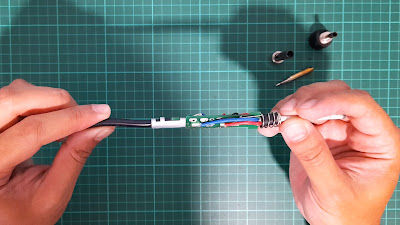
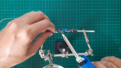
  10. Install a button switch at S1 and a battery box or a USB power wire. Note: the red wire connects to ‘+’, and the black wire connects to ‘-’. Solder the button and battery box wire.


  11. Insert the battery and test the button switch. One of the LEDs was damaged at L6. But, I do not have any spare LED to replace.


  12. Next, test using IR remote. Seem all functions working normally.
  13. Install battery box on PCB using M2 screw and nuts. Manage the battery wire using tape.
  14. Separate the protective film on the black acrylic surface.
  15. Install M3 copper cylinders and M3 nuts on PCB.
  16. Install lampshade and fix it using the fixed plate and M3 screws.


  17. Insert the battery.

  18. The DIY Kit Infrared Remote Control works like a charm.

Video:


That all from me. If you have any suggestions, please write in the comment section. Thank you for your time 👷.

Tuesday, December 21, 2021

How to Diagnose and Repair Soldering Iron Not Heating Up | Temperature | SAIKE 952D

Today, I want to show you how to diagnose and repair a soldering iron that not heating up. For your information, I use the original heating element A1321 from Hakko and rework station SAIKE 932D.

Step 1: Diagnosis soldering iron

  1. My handle soldering iron malfunctioned. I need to bend the cable cord to start increasing the temperature.


  2. If the cable cord is straightened, the temperature will not increase.
  3. I will show you how to repair squeaking noise problems in this post.
Step 2: Removal/Troubleshoot of a soldering iron handle
  1. Remove 5 pin soldering iron connector from the work station.


  2. Remove nut → tip enclosure → tip → nipple → handle → cable cord sleeve.


  3. The soldering job is poorly done, and the wires are folded from the surface view.


  4. Measure the resistance of the A1321 sensor and heating element. If the value is outside the acceptable range, replace it. If the resistance value is normal, the cable cord may be broken.


  5. After troubleshooting, the heat element resistance not detectable (OL) mean
    open load or open circuit.

  6. So, I decided to desolder the wire cord connected to the terminal board.


  7. Test continuity and resistance of each wire. Every pin and wire should have continuity and resistance within the range.


  8. However, pin 2 has no continuity and resistance (OL). When I bend the cable cord, pin 2 has resistance and continuity. If I straightened the cable cord, pin 2 had no resistance and continuity. 

  9. The root of the cause is a blue wire cord broken at the bend place. Cut the broken cable cord around 5 - 8 cm. 


  10. Remove the broken cable cord from the terminal board.


  11. Remove wire sleeve according to the broken wire length. 


  12. Test continuity and resistance of each wire. All wires are in good condition within the resistance tolerance and have continuity. 


  13. Prepare and clean the terminal board pinhole. Use isopropyl alcohol to clean the terminal board from resin and dust accumulated. 


  14. Place the wire in its place and solder. 


Step 2: Installation
  1. Bend metal cable cord holder.


  2. Install the handle components in reverse order of removal. 


  3. Measure the resistance values at the sensor and heating element of the terminal board. The sensor and heating element resistance values are within the range. 


  4. Install the cable cord sleeve. 


  5. Connect the 5 pin connector to work station and test the soldering iron. 


  6. Turn ON soldering iron and test increasing temperature. 


  7. The temperature rise in normal condition. 


  8. However, I do not have a thermocouple to measure the tip temperature. Overall it works like a charm. 


The link tools and components replacement I used in this video are listed below:

Tools/Components/Items (Lazada):

Video:


That all from me. If you have any suggestions, please write in the comment section. Thank you for your time 👷.