Tuesday, January 25, 2022

How to Change Steering Cone & Main Switch Motorcycle | Lock | Stem | SYM 125 Jet Power

Today, I want to show you how to change or replace the steering cone and main switch motorcycle SYM 125 Jet Power. Two replacement parts as mentioned below:

  1. Main switch replacement when the main switch malfunctions, such as the main switch stuck, lost key, and switch lock is loose, causing the motorcycle not to start or suddenly turn off when driving.
  2. Steering cone replacement when the steering stem has problems such as broken bearing steering stem that can be causing hard to turn right and left or wobbling when handling.

References:
Step 2: Removal
  1. Disassemble the body cover in sequence, as shown in the figure below. You can watch my previous video or post on removing body cover step by step.


  2. Disconnect 6 pin main switch connector, then remove wire harness.


  3. Loosen the adjustment nut of the rear brake arm and remove the rear brake cable.


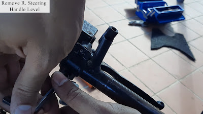
  4. Remove throttle housing screw, then remove the handle grip. Then, remove two-socket bolts of a rear steering handle level.


  5. Remove flange bolt between steering handle and stem. Then, pull out a steering handle.


  6. Remove the wheel axle nut and pull out the axle. Then, remove the front wheel.


  7. Remove the front fender by removing two flange bolts.


  8. Remove two flange bolts and the caliper.


  9. Remove steering stem lock nut → steering top cone race → steel ball → steering upper ball race. Then, remove steering bottom ball race → steel ball → steering bottom cone race → steering head dust seal → steering head dust seal washer.


  10. Remove the two flatlock screws and the main lock switch.


  11. Remove in sequence lock key set SPR -> seat lock stay -> seat lock.


Step 2: Installation
  1. Install all parts in reverse order of removal. Note: Apply with some thread locker at flat lock screw main switch.


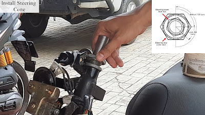
  2. Apply some grease onto the top and bottom bearing balls and cone race.


  3. Return 1/2 turn of the steering top cone race, then tighten again 1/4 turn or 2 N.m torque. Tighten steering stem lock nut 10 N.m.


  4. Apply some thread locker at the flange bolt steering handle.


  5. Apply some thread locker at flange bolt brake caliper.


  6. Apply some grease onto the bearing wheel.


  7. Turn the front brake adjustment nut to adjust the free play if necessary.

Step 3: Test
  1. For the main switch, test to lock and start the motorcycle.
  2. To test the steering cone, drive the motorcycle. If the steering handle wobbling tightens the steering top cone race and steering stem lock-nut.

The link tools and components replacement I used in this video are listed below:

Tools/Components/Items (Shopee):

  1. Spanner Set
  2. Screwdriver Set
  3. Allen Key Set
  4. SYM 125 Jet Power Main Switch Set
  5. SYM 125 Jet Power Steering Cone Set

Tools/Components/Items (Lazada):
Video:


That all from me. If you have any suggestions, please write in the comment section. Thank you for your time 👷.

Friday, January 14, 2022

How to Reset Perodua Axia Service Reminder Appear at Display | Spanner Symbol

Today, I will share how to reset the Perodua Axia service reminder appearing at the display/dashboard. The spanner symbol appears at the odometer, trip, and other selection displays when you reach10000km driving. It acts as a reminder to send your car to the Perodua service center or change engine oil. Usually, the Perodua service center will reset after serving your car. However, if you DIY or go to a different service center, you need to reset yourself.


Reference:
Steps (Reset ):
  1. The spanner symbol appears at the odometer, trip, and other selection displays when you reach10000km driving. It acts as a reminder to send your car to the Perodua service center or change engine oil. Usually, the Perodua service center will reset after serving your car. However, if you DIY or go to a different service center, you need to reset yourself.


  2. Push the reset button until you see '-----' or service information setting display.


  3. Push and hold the reset button for more than 3 seconds or until 'cLEAr' is displayed on the screen.


  4. The 'cLEAr' will blink 3 times, and it will restart the count to '10000km'. Once finished, you can change your desired display, e.g., odometer, trip meter, and others.


  5. The spanner symbol will appear again after you drive 10000km to remind you to go to the service center or change engine oil.


Video:


If you have any suggestions, please write in the comment section. Thank you for your time 👷.

Saturday, January 8, 2022

How to Add, Use and Interface RTC DS3231 DS3232 Module to Proteus 8 | Simulation | Circuit

Today, I will share how to add, use and interface the RTC DS3231 and DS3232 in Proteus 8 software. In Proteus 8, no IC DS3231 is found in the library, so I used IC DS3232 since it is very similar to the IC DS3231. The typical circuit is based on the RTC ZS-042 module, including IC DS3231 and I²C EEPROM 24C32. The basic circuit is used for simulation purposes in proteus only. A simple library (Rtc by Makuna) that makes interfacing DS1302, DS1307, DS3231, and DS3234 Real Time Clock modules was created by Michael C. Miller. 


References:

Components:

  1. Arduino UNO R3
  2. Cell
  3. Resistor
  4. LED
  5. IC DS3232 or DS3231
  6. IC 24C32A
  7. Diode

Steps (Typical Circuit):
  1. Open your Proteus software and add ARDUINO UNO R3, CELL, RESISTOR, LED, DS3232,  24C32A, VIRTUAL TERMINAL, and DIODE components to the workspace for the typical circuit.


  2. Connect VBAT to diode negative and positive to a resistor (200Ω). Then, the resistor (200Ω) is connected to the POWER. Next, connect POWER  to LED positive to the POWER and negative to a resistor (1kΩ). The resistor (1kΩ) is connected to the GND and VBAT to cell positive and negative to GND.


  3. Connect DEFAULT to the IC DS3232 pins SCL, SDA, 32KHz, and INT/SQW. Edit DEFAULT of IC DS3232 string according to the pins name of IC DS3232. Then, connect the pull-up resistor (4.7kΩ) to the IC DS3232 pins SCL, SDA, 32KHz, and INT/SQW. 


  4. Connect DEFAULT to the IC 24C32A SCL and SDA pins. Edit DEFAULT string of SCK and SDA to the SCL and SDL. Then, connect the WP pin to the GND. Then, connect the pull-up resistor (4.7kΩ) to the IC 24C32A pins A0, A1, and A2. 


  5. Connect switch (N/O)  to the IC 24C32A pins A0, A1, and A2. Then connect the switch to the GND.


  6. Connect DEFAULT to the A4, A5, and 2 pins of the Arduino UNO R3. Edit DEFAULT string Arduino UNO R3 pins A4, A5, and 2 to the SDA, SCL, and SQW. Lastly, connect VIRTUAL TERMINAL RXD and TXD to the  ARDUINO UNO R3 pins 1 and 0.


  7. Open Arduino IDE and go to Sketch > Include Library > Manage Libraries. Type 'Rtc by Makuna' on the search box and install it.


  8. Go to File > Examples > Rtc by Makuna > DS3231_Simple. Verify and copy the Hex file, then paste it into the Project file Arduino board.


  9. Start the simulation, and the VIRTUAL TERMINAL will display the date, time, and temperature. For the first time,  you will see VIRTUAL TERMINAL print "RTC lost confidence in the DateTime!". It will automatically update the date, time, and temperature every 10 seconds.


  10. To change the temperature in simulation, go to IC DS3232 > Double Click > Nominal Temperature > Change to your desired temperature > Press OK.


  11. Start the simulation and see the temperature change to the desired temperature.


Steps (Basic Circuit):
  1. For basic circuit simulation, remove all components except Arduino UNO R3 with DEFAULT pins, Virtual Terminal, and IC DS3232 with DEFAULT pins.


  2. Start the simulation, and the VIRTUAL TERMINAL will print out the same as the typical circuit simulation.


  3. Change the temperature to test out and start the simulation again.


Video:


If you have any suggestions, please write in the comment section. Thank you for your time 👷.

Monday, January 3, 2022

Adjustable 2 Jaws Bearing Puller Tool Carbon Steel | Rama Claw | Remover | Review

I ordered 2 jaws bearing pullers (Rama claws) from the online retailer, and I reviewed this tool today. The jaw puller is used to pull off the bearings, couplings, gears, armature, and pulley without damaging them. For your information, this post is not sponsored.


Review 2 Jaws Puller

  1. I bought a 4" or 100 mm 2 jaws puller from an online retailer. It comes in many sizes, 2" up to 10 " or 50 mm to 250mm.
  2. The center bolt threads are designed for less effort when applying high torque. The crossbar bolt is removable to fit the part to remove, and the material used is high-carbon steel, and the color is black.
Step 2: Test
  1. For testing purposes, I gonna remove the bearing ceiling fan from the shaft.


  2. First, select the proper size of 2 jaw pullers and fit the bearing or the part to be removed.


  3. I slide the spanner to the shaft since my shaft hole is bigger than the center bolt to prevent it from losing when fitted. Turn the center bolt until it touches the center shaft or spanner.


  4. Fit the crossbar tightly.


  5. In my case, I turn the center bolt slowly and carefully, applying force onto the shaft or spanner.


  6. When the pulling part or bearing is off from the shaft, remove the 2 jaws puller.


  7. No damage to the bearing and shaft after removal.


The link tools and components replacement I used in this video are listed below:

Tools/Components/Items (Shopee):

  1. Screwdriver Set
  2. Plier Set
  3. Jaws Puller (4 Inches)
  4. Spanner Set
  5. Bearing (6203ZZ)

Tools/Components/Items (Lazada):
Video:


That's all from me. If you have any suggestions, please write in the comment section. Thank you for your time 👷.