Wednesday, February 23, 2022

PIR Motion Sensor Based Home Security System using Arduino | Project | Proteus 8

Today, I will share a simple system to detect intruders/thieves using Arduino and PIR sensors. The PIR sensor is ideal for detecting human movement or occupancy in security systems. Download the project, library, and simulation files below.


How its work?

  1. The LCD will display "Alarm Security System" in the beginning, followed by  "LOADING **********".
  2. After loading the screen, the LCD will display "Alarm Activated".
  3. If the sensor detects movement, the LED light will blink, followed by a buzzer. Then, the LCD will display "Motion Detected Alarm Triggered".
  4. The BUZZER and LED are still ON even though the PIR sensor does not detect any movement after the alarm is triggered.
  5. Press the push button and ensure the PIR sensor did not detect any movement to reset the alarm. Then, the LCD will display "Alarm Reset" followed by "Alarm Activated".

Related Post:
References:

Components:

  1. PIR motion sensor
  2. LED
  3. Resistor
  4. Virtual terminal
  5. Logic state
  6. Pushbutton
  7. LCD I2C
  8. Buzzer

Steps
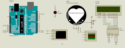
  1. Open Proteus 8 software and add PIR SENSOR, ARDUINO UNO R3, LED-RED, RESISTOR, BUZZER, SWITCH, LM016L, PCF8574, and LOGICSTATE components to the workspace.


  2. Wiring all the components according to the figure below.


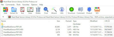
  3. Double click the PIR SENSOR and click the folder icon. Go to Local Disk (C:) > Program Files (x86) > Labcenter Electronics > Proteus 8 Professional > DATA > LIBRARY > PIRSensorTEP.HEX > Open > OK.


  4. Download the PROJECT file. Extract the project file and verify.


  5. Copy the Hex file, then paste it to the project file Arduino board.


  6. Double click the BUZZER and change operating voltage to 5V; load resistance to 100.


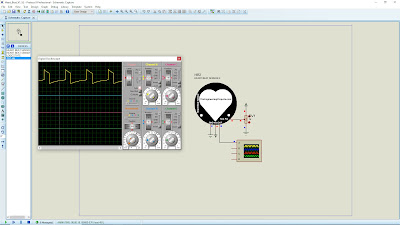
  7. Start the simulation, and the LCD will display "Alarm Security System" in the beginning, followed by  "LOADING **********".


  8. After loading the screen, the LCD will display "Alarm Activated".


  9. Toggle the LOGICSTATE to imitate the motion. (LOGICSTATE = 1 motion detected, LOGICSTATE = 0 motion not detected). If the sensor detects movement, the LED light will blink, followed by a buzzer. Then, the LCD will display "Motion Detected Alarm Triggered".


  10. The BUZZER and LED are still ON even though the PIR sensor does not detect any movement after the alarm is triggered.


  11. Press the push button and ensure the PIR sensor did not detect any movement to reset the alarm. Then, the LCD will display "Alarm Reset" followed by "Alarm Activated".


Video:


If you have any suggestions, please write in the comment section. Thank you for your time 👷.

Sunday, February 13, 2022

How to Add and Simulate PIR Motion Sensor in Proteus 8 | Passive Infrared | Arduino

Today, I will share how to add and simulate a PIR motion sensor with Arduino in Proteus 8 software. A passive infrared (PIR) motion sensor can detect any movement that radiates infrared light. It is ideal for detecting human movement or occupancy in security systems.


References:

Components:

  1. PIR motion sensor
  2. LED
  3. Resistor
  4. Virtual terminal
  5. Logic state

Steps (Add Library)
  1. Download the PIR motion sensor library file at TheEngineeringProjects.com or click the link HERE. The download link will appear after 20 seconds.

  2. You will find three files on the downloaded zip file, named as:
    -PIRSensorTEP.LIB
    -PIRSensorTEP.IDX
    -PIRSensorTEP.HEX


  3. Extract these three files to the Proteus libraries folder (C:\Program Files (x86)\Labcenter Electronics\Proteus 8 Professional\DATA\LIBRARY).

Steps (PIR Motion Sensor):
  1. Open your Proteus software and add PIR SENSOR, ARDUINO UNO R3, LED-RED, RESISTOR, VIRTUAL TERMINAL, and LOGICSTATE components to the workspace.


  2. Wiring components:
    -Connect VCC, OUT, GND, and Test Pin of sensor pins to the POWER, digital pin 3 (Arduino), GROUND, and LOGICSTATE.
    -Connect RXD and TXD (VIRTUAL TERMINAL) to the TXD and RXD (Arduino).
    -Connect LED from pin 13 Arduino to GROUND through 220 Ω resistor.


  3. Click HERE to download the Arduino project code. Extract the project code and verify. 


  4. Copy the Hex file, then paste it into the Proteus Arduino board.


  5. Double click the PIR SENSOR and click the folder icon at the Program File box. Go to Local Disk (C:) > Program Files (x86) > Labcenter Electronics > Proteus 8 Professional > DATA > LIBRARY > PIRSensorTEP.HEX > Open > OK.


  6. Start the simulation. In the beginning, 10 seconds delay is added to calibrate the sensor, and the serial will print out "Calibrating sensor ..........". After 10 seconds, the serial will print out "done" and "SENSOR ACTIVE".


  7. Toggle the LOGICSTATE to imitate the motion. (LOGICSTATE = 1 motion detected, LOGICSTATE = 0 motion not detected). If the sensor detects movement, the LED light will turn ON, and the serial will print out "motion detected at xxx sec".


  8. If no movement detects < 5 seconds, the LED light will turn OFF.


  9. If no movement detects > 5 seconds, the serial will print out "motion ended at xxx sec".


Video:


If you have any suggestions, please write in the comment section. Thank you for your time 👷.

Monday, February 7, 2022

Heart Rate Monitoring System using Arduino | Pulse Heart Sensor | BPM | Project | Proteus 8

Today, I will share a simple heart rate or pulse rate monitoring system using Arduino. The sensor is used to measure a person's heartbeat rate or heartbeat count. The library I used for this project is from PulseSensor Playground. Download the project, library, and simulation files below.


How its work?

  1. The sensor will sense the heartbeat and display it on the serial communication and LCD.
  2. Display "A Heart Beating!" and "BPM: ". The data update automatically when a beat is detected.
  3. Blink LED on PIN 13 when a beat is detected.
  4. Change the heartbeat pattern by increasing or decreasing the variable resistor.

Related Post:
References:

Components:

  1. Heart Beat Sensor V2
  2. Variable Resistor
  3. Oscilloscope
  4. LCD 16 × 2 I2C
  5. Arduino UNO
  6. LED

Steps
  1. Open Proteus 8 software and add  ARDUINO UNO R3, HEART BEAT SENSOR 2, LED-RED, POT-HG, LM016L, VIRTUAL TERMINAL, OSCILLOSCOPE, and PCF8574 to the workspace.


  2. Wiring all the components according to the figure below.


  3. Double click the HEART BEAT SENSOR 2 and click the folder icon. Go to Local Disk (C:) > Program Files (x86) > Labcenter Electronics > Proteus 8 Professional > DATA > LIBRARY > HeartBeatSensorTEP2.HEX > Open > OK.


  4. Download the LIBRARY and PROJECT file. Extract the project file and verify.


  5. Copy the Hex file, then paste it to the project file Arduino board.


  6. Start the simulation and set the time scale of the oscilloscope to 0.4μS. The LCD and serial communication will display "A Heart Beating!" and "BPM: " when the heartbeat is detected. 


  7. The heartbeat rate (BPM) will increase if the resistance value decreases.


  8. The heartbeat rate (BPM) will decrease if the resistance value increases.


Video:


If you have any suggestions, please write in the comment section. Thank you for your time 👷.

Tuesday, February 1, 2022

How to Add and Simulate Heart Beat Sensor in Proteus 8 | Pulse Heart Rate | AD8232 Module

Today, I will share how to add and simulate a heartbeat or pulse heart rate sensor in Proteus 8 software. The heartbeat sensor is used to measure a person's heartbeat rate or heartbeat count. There got two versions of the heartbeat sensor:

  1. Heart Beat Sensor V1 - Static heartbeat pattern by toggling the LOGICSTATE to turn ON and OFF.
  2. Heart Beat Sensor V1 - Variable heartbeat pattern by increasing or decreasing the variable resistor.


References:

Components:

  1. Heart Beat Sensor V1
  2. Heart Beat Sensor V2
  3. Variable Resistor
  4. Oscilloscope

Steps (Add Heart Beat V1 and V2 Library)
  1. Download the Flame Sensor library file at TheEngineeringProjects.com or click the link HERE. The download link will appear after 20 seconds.

  2. You will find four files on the downloaded zip file, named as:
    -HeartBeatSensorTEP.LIB
    -HeartBeatSensorTEP.IDX
    -HeartBeatSensorTEP.HEX
    -HeartBeatSensorTEP2.HEX


  3. Extract these four files to the Proteus libraries folder (C:\Program Files (x86)\Labcenter Electronics\Proteus 8 Professional\DATA\LIBRARY).

Steps (Heart Beat Sensor V1):
  1. Open your Proteus software and add HEART BEAT SENSOR and LOGICSTATE components to the workspace.


  2. Add POWER, GROUND, and  DC VOLTMETER.


  3. Connect GND, VCC, OUT, and Test Pin of sensor pins to the GROUND, POWER, DC VOLTMETER ( + to OUT and - to GND), and LOGICSTATE.


  4. Double click the infrared sensor and click the folder icon at the Program File box. Go to Local Disk (C:) > Program Files (x86) > Labcenter Electronics > Proteus 8 Professional > DATA > LIBRARY > HeartBeatSensorTEP.HEX > Open > OK.


  5. Start the simulation. Toggle the LOGICSTATE to imitate the heartbeat.


  6. If LOGICSTATE is HIGH, then DC VOLTAGE shows 5V. 


  7. When LOGICSTATE is LOW, then DC VOLTAGE show 0V.


Steps (Heart Beat Sensor V2):
  1. For Heart Beat Version 2 Simulation, add HEART BEAT SENSOR 2 and POT-HG components to the workspace.


  2. Add POWER, GROUND, and OSCILLOSCOPE.


  3. Connect GND and VCC of sensor pins to the GROUND and  POWER. Then, connect the Test Pin of the sensor pin to the wiper pin to the POT-HG and ends to the POWER and GROUND. Lastly, connect the A pin to the OUT pin of the sensor.


  4. Double click the infrared sensor and click the folder icon at the Program File box. Go to Local Disk (C:) > Program Files (x86) > Labcenter Electronics > Proteus 8 Professional > DATA > LIBRARY > HeartBeatSensorTEP2.HEX > Open > OK.


  5. Start the simulation and set the time scale to 0.4μS and voltage scale to 2mV for channel A.
     

  6. The heart beat rate will increase if the resistance value decreases, as seen in the oscilloscope.


  7. The heart beat rate will decrease if the resistance value increases, as seen in the oscilloscope.


Video:


If you have any suggestions, please write in the comment section. Thank you for your time 👷.