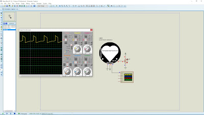
Today, I will share how to add and simulate a heartbeat or pulse heart rate sensor in Proteus 8 software. The heartbeat sensor is used to measure a person's heartbeat rate or heartbeat count. There got two versions of the heartbeat sensor:
- Heart Beat Sensor V1 - Static heartbeat pattern by toggling the LOGICSTATE to turn ON and OFF.
- Heart Beat Sensor V1 - Variable heartbeat pattern by increasing or decreasing the variable resistor.
References:
Components:
- Heart Beat Sensor V1
- Heart Beat Sensor V2
- Variable Resistor
- Oscilloscope
Steps (Add Heart Beat V1 and V2 Library)
- Download the Flame Sensor library file at TheEngineeringProjects.com or click the link HERE. The download link will appear after 20 seconds.
- You will find four files on the downloaded zip file, named as:
-HeartBeatSensorTEP.LIB
-HeartBeatSensorTEP.IDX
-HeartBeatSensorTEP.HEX
-HeartBeatSensorTEP2.HEX - Extract these four files to the Proteus libraries folder (C:\Program Files (x86)\Labcenter Electronics\Proteus 8 Professional\DATA\LIBRARY).
Steps (Heart Beat Sensor V1):
- Open your Proteus software and add HEART BEAT SENSOR and LOGICSTATE components to the workspace.
- Add POWER, GROUND, and DC VOLTMETER.
- Connect GND, VCC, OUT, and Test Pin of sensor pins to the GROUND, POWER, DC VOLTMETER ( + to OUT and - to GND), and LOGICSTATE.
- Double click the infrared sensor and click the folder icon at the Program File box. Go to Local Disk (C:) > Program Files (x86) > Labcenter Electronics > Proteus 8 Professional > DATA > LIBRARY > HeartBeatSensorTEP.HEX > Open > OK.
- Start the simulation. Toggle the LOGICSTATE to imitate the heartbeat.
- If LOGICSTATE is HIGH, then DC VOLTAGE shows 5V.
- When LOGICSTATE is LOW, then DC VOLTAGE show 0V.
Steps (Heart Beat Sensor V2):
- For Heart Beat Version 2 Simulation, add HEART BEAT SENSOR 2 and POT-HG components to the workspace.
- Add POWER, GROUND, and OSCILLOSCOPE.
- Connect GND and VCC of sensor pins to the GROUND and POWER. Then, connect the Test Pin of the sensor pin to the wiper pin to the POT-HG and ends to the POWER and GROUND. Lastly, connect the A pin to the OUT pin of the sensor.
- Double click the infrared sensor and click the folder icon at the Program File box. Go to Local Disk (C:) > Program Files (x86) > Labcenter Electronics > Proteus 8 Professional > DATA > LIBRARY > HeartBeatSensorTEP2.HEX > Open > OK.
- Start the simulation and set the time scale to 0.4μS and voltage scale to 2mV for channel A.
- The heart beat rate will increase if the resistance value decreases, as seen in the oscilloscope.
- The heart beat rate will decrease if the resistance value increases, as seen in the oscilloscope.
Video:
If you have any suggestions, please write in the comment section. Thank you for your time 👷.


No comments:
Post a Comment