Monday, October 25, 2021

Diagnose and Repair Motorcycle (Scooter) Hard to Start | Replace Spark Plug | SYM Jet Power 125

Today, I want to show you how to diagnose and repair scooter SYM Jet Power 125 hard to crank/start due to a faulty spark plug. Here are some common symptoms of the faulty spark plug or bad spark plug, e.g., hard to start, engine run sluggish, no spark produced by the spark plug, the engine does not crank smoothly, etc.

References:

Step 1: Removal of Battery
  1. Disassemble the body cover in sequence 1 → 2 → 3 as shown in the figure below. You can watch my previous video or post on how to remove body cover step by step.


  2. Remove spark plug cap.


  3. Use spark plug spanner and rotate anti-clockwise to remove the spark plug.


  4. Test the spark plug by reconnecting the spark plug cap, then position the plug to the engine body. 
    • Replace the spark plug if the spark produced is weak.
     The bad spark plug on the right side is a bad or burnt spark plug that needs replacement.
    • 
    Measure the spark plug gap if the gap is less than 0.6 mm, then replace the spark plug.

     
Step 2: Installation
  1. Install the spark plug in reverse order of removal.

The link tools and components replacement I used in this video are listed below:

Tools/Components/Items (Shopee):

  1. Spanner Set
  2. Screwdriver Set
  3. Tube Bar Spark Plug Spanner
  4. Spark Plug (C7HSA)

Tools/Components/Items (Lazada):

Video:


That all from me. If you have any suggestions, please write in the comment section. Thank you for your time 👷.

Sunday, October 17, 2021

How to Add, Use and Interface Flame Sensor Library to Proteus 8 | Fire Sensor

Hi guys, today I will share how to add, use and interface the flame sensor library in Proteus 8 software. The library is based on a flame sensor from TEP. A simple project code was created by me to detect fire or flame from a flame sensor. 


Flame Sensor Applications:

  • Fire detection
  • Fire alarm
  • NPG storage 
  • Engine room
  • Flame monitors
  • Power station
  • Etc

Components:

  • Flame sensor
  • Arduino
  • Resistor
  • LED

Steps (Flame Sensor Library)
  1. Download the Flame Sensor library file at TheEngineeringProjects.com or click the link HERE. The download link will appear after 20 seconds.

  2. You will find three files and one folder on the downloaded zip file, named as:
    -FlameSensorsTEP.IDX
    -FlameSensorsTEP.LIB
    -FlameSensorsTEP.HEX
    -Proteus Simulation


  3. Extract FlameSensorsTEP.IDX, FlameSensorsTEP.LIB, and FlameSensorsTEP.HEX files to the Proteus libraries folder (C:\Program Files (x86)\Labcenter Electronics\Proteus 8 Professional\DATA\LIBRARY).

  4. Open your Proteus software and search for the Flame Sensor component.


  5. Double click and drag to add to the Proteus 8 workspace.


Steps (Standalone):
  1. Open your Proteus software and add infrared sensor, resistor, LED and LOGICSTATE to the workspace.


  2. Connect GND, VCC, TestPin pins to the ground, power, and LOGICSTATE. Connect LED from pin OUT to ground through a resistor.


  3. Double click the infrared sensor and click the folder icon at the Program File box. Go to Local Disk (C:) > Program Files (x86) > Labcenter Electronics > Proteus 8 Professional > DATA > LIBRARY > InfraredSensorsTEP.HEX > Open > OK.


  4. Start the simulation 

  5. If LOGICSTATE = 0, flame sensor not detect any flame. If LOGICSTATE = 1, flame sensor detect flame. 

  6. LED ON when flame detected by a flame sensor and LED OFF when flame sensor not detected flame.

Steps (Flame Sensor with Arduino):
  1. Add  Arduino UNO R3 component to the workspace

  2. Change flame sensor OUT pin to the pin 2 Arduino and connect LED from pin 13 to ground through a resistor.


  3. Click HERE to download the Arduino project code. Extract the project code and verify

  4. Copy the Hex file, then paste it into the Proteus Arduino board.


  5. Start the simulation

  6. LED ON when flame detected by a flame sensor and LED OFF flame sensor not detected flame.

Video:


If you have any suggestions, please write in the comment section. Thank you for your time 👷.

Saturday, October 9, 2021

Diagnose and Repair Motorcycle (Scooter) No Power Supply | Won't Start | SYM Jet Power 125

Today, I want to show you how to diagnose and repair a wire harness problem due to corrosion. Here are some common symptoms for such a problem, e.g. no power supply, intermittent power supply, the starter motor does not work, a motorcycle suddenly turns off while running, etc.

References:

Step 1: Removal of Battery
  1. I only can find the SYM Jet 4 125 wiring diagram on the internet. It is very similar to the SYM Jet Power 125. Used multimeter to check the battery voltage. The black probe is negative, and the red probe is positive. The measurement I got from the battery is 12 V within the required voltage range. So, my battery is in good condition.

  2. Move the positive probe to the first side fuse and check the voltage. The measurement I got from the first side fuse is 12 V within the required voltage range. So, connection or wire in good condition.
  3. The measurement I got from the second side fuse is 12 V within the required voltage range. So, the fuse is in good condition. Repeat the same measurement for another side of the fuse.
  4. Next, move the positive probe to the 6 pin connector. Measure the red wire from the connector. I got 6 V that is below the required voltage. This means the connection/wire between fuse and connector problem.
    Redline indicate the faulty wire.

Step 2: Remove Wire Harness
  1. First, you need to disassemble body covers. You can watch my previous video or post on how to remove body cover step by step.

  2. Remove wire harness.

    Untie wire harness at right side body cover.

    Unclip wire harness at the front inner cover

    Unclip wire harness at the front cover

    Disconnect CDI connector

    Disconnect resistor connector

    Disconnect rectifier connector

    Disconnect 4 and 9 pins connector

    Disconnect 6 pins connector

    Remove negative and positive lead of the battery.

    Disconnect connector that connected to the wire harness

    Unclip and disconnect the connector at the right side of the body cover

Step 3: Remove Insulate Wire Harness

  1. Remove insulate and identify the problem.

    The jointing/connection between these wires is corrosion.

    Zooming

Step 4: Solder and Insulate Wire Harness
  1. Cut and remove any corrosion on the wire and jointing the wire together. Remove insulate and identify the problem.

    Jointing and solder wire

  2. Install heat shrink tube and use hot glue to prevent corrosion to the joint wire due to the fluid/moisture.

    Cover the exposed solder with heat shrink

    Hot glue heat shrink

  3. Insulate the wire harness using black tape and a flexible tube.


Step 4: Installation
  1. Install wire harness in reverse order of removal.

  2. Lastly, assemble body covers. You can watch my previous video or post on how to install body cover step by step.

The link tools and components replacement I used in this video are listed below:

Tools/Components/Items (Shopee):

  1. Spanner Set
  2. Screwdriver Set
  3. Allen Key Set
  4. Solder Core Wire (0.6mm)
  5. Solder Flux
  6. Tweezer ESD
  7. Soldering Iron (ZD90S)
  8. Multimeter UNI-T UT210E
  9. Electrical Tape
Tools/Components/Items (Lazada):
  1. Spanner Set
  2. Screwdriver Set
  3. Allen Key Set
  4. Solder Core Wire (0.6mm)
  5. Solder Flux
  6. Tweezer ESD
  7. Soldering Iron (ZD90S)
  8. Multimeter UNI-T UT210E
  9. Electrical Tape
Tools/Components/Items (Aliexpress):
Video:


That all from me. If you have any suggestions, please write in the comment section. Thank you for your time 👷.

Tuesday, October 5, 2021

How to Remove and Install SYM 125 Jet Power Body Covers | Teardown | Disassemble | Assemble

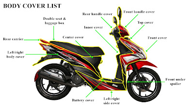
Today, I want to show you how to remove and install SYM 125 Jet Power body covers. The body covers include front handle cover, rear handle cover, top cover, front cover, inner cover, front under spoiler, left/right side cover, battery cover, center cover, luggage box, double seat, rear carrier, and left/right body cover.


DISASSEMBLE BODY COVERS
Body Covers Disassembly or Removal Sequence:

    Step 1: Front and Rear Handle Cover
    1. Remove left and right back mirror
    2. Remove 3 screws at the front handle cover.
    3. Remove 5 screws at the rear handle cover.
    4. Remove meter garnish using a pry tool or flat screwdriver.

    5. Pry the left and right back mirror to remove the front handle cover.

    6. Remove 4 screws at the inner rear handle cover.


    7. Remove winkey relay and LED control unit.


    Step 2: Top and Front Cover
    1. Rotate anti-clockwise to open the main switch cap.
    2. Remove 12 screws at the inner cover and 3 screws at the rack.

    3. Remove the top cover and 2 mounting bolts at the front cover.

    4. Remove 4 screws between the front under the spoiler and the frame.


    5. Remove front cover and 2 connectors attached.
    Step 3: Left and Right Side Cover
    1. Remove 8 screws located and left, right, and bottom side cover.


    2. Remove 2 screws at the bottom under the spoiler.
    3. Then, remove the left and right side cover.

    Step 4: Front Under Spoiler and Inner Cover
    1. Remove 2 screws between front under spoiler and inner cover.

    2. Remove the front under the spoiler.


    3. Remove 4 screws at the inner cover and floor panel, then remove the inner cover.


    4. Remove 4 screws at the bottom under the spoiler.


    Step 5: Double Seat and Luggage Box
    1. Remove 6 screws at the luggage box and a screw front double seat.

    2. Remove double seat with luggage box.
    Step 6: Battery and Center Cover
    1. For battery removal, please go to my previous POST.
    2. Remove 2 screws at the bottom center cover and 2 screws at the side center cover.


    3. Remove center cover.

    Step 7: Rear Carrier
    1. Remove 4 Allen key bolts at the rear carrier.
    2. Remove rear carrier.

    Step 8: Left and Right Cover

    1. Remove these 2 screws at the tail light.
    2. Remove 2 screws at the license plate and 2 screws at the rear fender.

    3. Remove 4 screws at the inner rear fender.

    4. Remove 2 screws at the inner body cover.

    5. Pull body cover and remove connectors attached to the body cover.

    6. Remove seat lock cable.
    ASSEMBLE BODY COVERS
    Body Covers Assembly or Installation Sequence:


    Step 1: Body Covers
    1. Install body covers in reverse order of removal.

    The link tools and components replacement I used in this video are listed below:

    Tools/Components/Items (Shopee): 1. Spanner Set 2. Screwdriver Set 3. Allen Key Set Tools/Components/Items (Lazada): 1. Spanner Set 2. Screwdriver Set 3. Allen Key Set Tools/Components/Items (Aliexpress): 1. Spanner Set 2. Screwdriver Set 3. Allen Key Set

    Video:


    That all from me. If you have any suggestions, please write in the comment section. Thank you for your time 👷.