Today, I want to show you how to diagnose and repair a wire harness problem due to corrosion. Here are some common symptoms for such a problem, e.g. no power supply, intermittent power supply, the starter motor does not work, a motorcycle suddenly turns off while running, etc.
- I only can find the SYM Jet 4 125 wiring diagram on the internet. It is very similar to the SYM Jet Power 125. Used multimeter to check the battery voltage. The black probe is negative, and the red probe is positive. The measurement I got from the battery is 12 V within the required voltage range. So, my battery is in good condition.
- Move the positive probe to the first side fuse and check the voltage. The measurement I got from the first side fuse is 12 V within the required voltage range. So, connection or wire in good condition.
- The measurement I got from the second side fuse is 12 V within the required voltage range. So, the fuse is in good condition. Repeat the same measurement for another side of the fuse.
Step 2: Remove Wire Harness
- First, you need to disassemble body covers. You can watch my previous video or post on how to remove body cover step by step.
- Remove wire harness.
Untie wire harness at right side body cover. Unclip wire harness at the front inner cover Unclip wire harness at the front cover Disconnect CDI connector Disconnect resistor connector Disconnect rectifier connector Disconnect 4 and 9 pins connector Disconnect 6 pins connector Remove negative and positive lead of the battery. Disconnect connector that connected to the wire harness Unclip and disconnect the connector at the right side of the body cover
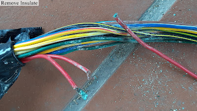
Step 3: Remove Insulate Wire Harness
Step 4: Solder and Insulate Wire Harness
- Cut and remove any corrosion on the wire and jointing the wire together. Remove insulate and identify the problem.
Jointing and solder wire - Install heat shrink tube and use hot glue to prevent corrosion to the joint wire due to the fluid/moisture.
Cover the exposed solder with heat shrink Hot glue heat shrink - Insulate the wire harness using black tape and a flexible tube.
Step 4: Installation
The link tools and components replacement I used in this video are listed below:
Tools/Components/Items (Shopee):
- Spanner Set
- Screwdriver Set
- Allen Key Set
- Solder Core Wire (0.6mm)
- Solder Flux
- Tweezer ESD
- Soldering Iron (ZD90S)
- Multimeter UNI-T UT210E
- Electrical Tape
Video:
That all from me. If you have any suggestions, please write in the comment section. Thank you for your time 👷.


No comments:
Post a Comment