Today, I will share how to add and use NodeMCU V3 with Arduino IDE. The installed ESP8266 board manager is applied to all ESP8266 brands such as Wemos D1, Wemos D1 R2, Robotdyn D1 R2, NodeMCU V3, etc. Furthermore, it comes with example libraries for ESP8266 boards.
Why use the ESP8266 board?
The main reason for using the ESP8266 board is because inexpensive able to connect to Wi-Fi and open-source IoT platforms.
Related Post:
Steps
Download the newest version of the CH340 driver from the WCH website. Click
HERE to download.
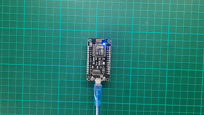
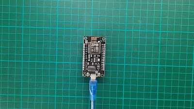
Connect NodeMCU Lua V3 to the PC or laptop via communication cable (USB to the micro USB).
Go to Control Panel > Device Manager, then you will see an unknown USB device pop up after you connect USB to PC.
The driver may install automatically on PC, and some may not. However, the installed version is not updated. To update or install manually, double click CH341SER.EXE, then click INSTALL.
Go to Control Panel > Device Manager. Then you will see USB-SERIAL CH340(COMXX) after the driver is installed.
Open Arduino IDE and go to File > Preferences > Additional Board Manager URLs > Enter https://arduino.esp8266.com/stable/package_esp8266com_index.json > OK.
Go to Tools > Board > Boards Manager > Type esp8266 > Select version > Install. If error downloading occur, click install again until successful. Then, click Close.
Go to Tools > Board > ESP8266 Boards > Select NodeMCU 1.0 (ESP-12E Module) and change Port to your COMXX (As mention in Device Manager CH340).
- For testing purposes, we simulate Blink code using the ESP8266 library. Go to File > Examples > ESP8266 > Blink. Verify the code and upload.
After the upload is done, you will see the onboard LED blink every second.
 |
| LED ON |
 |
| LED OFF |
For the next example, we use both onboard and external LEDs. Connect LED from pin D4 to the GROUND through 220 Ω resistor. Note BUILT-IN pin corresponding to pin D4. The onboard LED is active low, and the external LED is active high, causing the LEDs to blink in sequence.
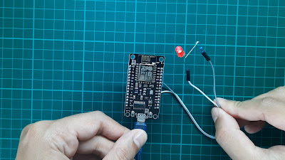 |
| LED ON |
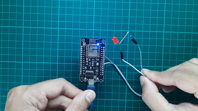 |
| LED OFF |
Tools/Components I used in this post are listed below:
Shopee:
Lazada:
Aliexpress:
If you have any suggestions, please write in the comment section. Thank you for your time 👷.