Thursday, April 27, 2023

How to Replace the Pressure Switch on a Panasonic Water Pump: Step-by-Step Guide

Do you have a Panasonic (A-130JACK) water pump running continuously, even when unused? This issue is often caused by a defective pressure switch, a prevalent problem for many homeowners. But, replacing the pressure switch on your water pump is easier than you may think. 

Panasonic water pump model A-130JACK

This detailed step-by-step guide provides an excellent tutorial that walks you through safely turning off the power to your pump, opening the connection cover, removing the old pressure switch, and installing a new one with PTFE tape. You can quickly and effortlessly fix your water pump by following the easy-to-understand instructions.


Step 1: Troubleshoot
  1. The water pump is constantly turning on even though water has been used for less than 5 minutes.

    The water pump constantly running

  2. The pressure switch must be broken. I need to replace it.
Step 2: Remove
  1. Turn off the power supply to the water pump and close the stop valve.

    Turn off switch

    Close the stop valve

  2. Remove the cover that protects the terminal connection points of the water pump.

    Open terminal cover

  3. Remove the cable clip.

    Remove cable clip

  4. Remove one wire to the neutral terminal block.

    Remove the wire from the terminal block

  5. Remove the other pressure switch wire to the capacitor by cutting it.
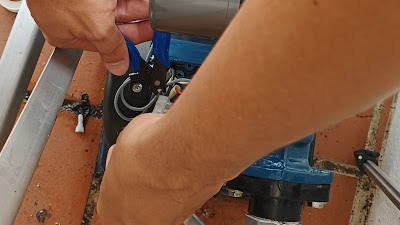
    Remove the wire from the capacitor

  6. Remove the pressure switch from the pump by rotating it counterclockwise.

    Remove pressure switch

  7. The original pressure switch from Panasonic had ON and OFF values of 1.1 kgf/cm² and 1.8 kgf/cm², respectively.

    Original pressure switch

  8. The replacement pressure switch from SANWA has ON and OFF values of 0.12 MPa and 0.24 MPa, respectively.

    Replacement pressure switch

Step 3: Install
    1. Apply PTFE tape to the threaded area.

      Apply PTFE tape

    2. Install the pressure switch by rotating it clockwise.

      Install the pressure switch

    3. Arrange and secure the wire using a cable clip.

      Install cable clip

    4. Connect one wire to the neutral terminal block.

      Install one wire to the terminal block

    5. Connect the other wire of the pressure switch to the capacitor by soldering it.

      Solder one wire to the capacitor

    6. Close the terminal cover of the water pump connection.

      Close the terminal cover

    Step 3: Test
        1. Open the stop valve and turn on the power supply to the water pump.

          Open the stop valve

          Turn on switch

        2. Great, the water pump is now turning on and off correctly. The new pressure switch has fixed the issue.

          Test water pump

        3. After ensuring everything is working fine and there is no leaking at the pressure switch connection, put the pump cover back on.

          Put the water pump cover

        The link tools and components replacement I used in this video is listed below:

        Friday, April 7, 2023

        How to Install the Lucky Wheel Sweepstakes DIY Kit from ICStation: Step-by-Step Tutorial

        Introducing the electronic lucky wheel sweepstakes soldering DIY kit. This sophisticated kit is designed to accurately simulate the workings of a lucky wheel. As the wheel spins, the LED will flash in an automated and decelerating pattern until it comes to a complete stop. Moreover, the speed of the LED flashing can be easily adjusted to suit individual preferences. For an added level of engagement, users can mark specific rewards on the white surface of the wheel.

        Lucky wheel from ICStation

        This intriguing DIY electronic product not only provides entertainment but also serves as an excellent educational tool for circuitry comprehension and soldering proficiency. In this formal article, we will comprehensively explore the notable features and diverse benefits of this unique and innovative DIY kit.

        Product/Reference:

        1. Lucky Wheel Kit - http://www.icstation.com/lucky-wheel-sweepstakes-electronic-soldering-p-15949.html

        Components:

        1. CD4017 DIP-16 IC - 1 pcs
        2. NE555 DIP-8 IC - 1 pcs
        3. IC socket DIP-16 - 1 pcs
        4. IC socket DIP-8 - 1 pcs
        5. Metal film resistors 10kΩ - 1 pcs
        6. Metal film resistors 470kΩ - 1 pcs
        7. Red LED 5mm - 10 pcs
        8. Electrolytic capacitor 220uF - 1 pcs
        9. Electrolytic capacitor 1uF - 1 pcs
        10. Self-locking switch - 1 pcs
        11. Switch button - 1 pcs
        12. Potentiometer 1MΩ - 1 pcs
        13. Transistor S9014 - 1 pcs
        14. CR2032 3V battery - 2 pcs
        15. CR2032 battery socket - 2 pcs
        16. PCB - 1 pcs
        Components list for lucky wheel

        Steps: Installation
        1. Install 1 pcs 470kΩ resistor at R3.


        2. Install 1 pcs 10kΩ resistor at R2.


        3. Install the DIP-8 IC Socket at U1, and match the gap mark on the PCB silkscreen with the gap mark on one end of the IC Socket. This will ensure that the IC Socket is placed in the correct direction.


        4. Install the DIP-16 IC Socket at U2, and align the gap mark on one end of the IC Socket with the gap mark on the PCB silk screen. These marks correspond to each other and indicate the correct installation direction for the IC Socket.


        5. Install the 2 CR2032 Battery Sockets, and consider the installation direction. If they are installed incorrectly, the battery will not fit properly.


        6. Install 1pcs Switch Button at S1.


        7. Install the TO-92 S9014 Transistor at Q1, and match the arc on the transistor with the arc on the PCB silk screen. This will ensure that the transistor is installed in the correct orientation.


        8. Install 1 pcs 1MΩ potentiometer at R13.


        9. Install a 1uF Electrolytic Capacitor at C2. It is important to distinguish between the positive and negative poles. The longer pin is the positive pole.


        10. Install 1 pcs Self-locking switch at KG.


        11. Install 10 pcs of 5mm Red LEDs at D1-D10 and distinguish between the positive and negative poles. The longer pin is the positive pole.


        12. Install a 220uF Electrolytic Capacitor at C1. It is important to distinguish between the positive and negative poles. The longer pin is the positive pole.


        13. Install the CD4017 and NE555 IC and align the gap mark on one end of the IC with the gap mark on the IC socket. These marks correspond to each other and indicate the correct installation direction for the IC.


        14. Write your name on the white area and then spin the Lucky Wheel.


        Steps: Tuning and Testing
        1. Find the tune that suits your preferences by adjusting the potentiometer. A duration of around 15 seconds for each game is ideal.

        2. Press the self-locking switch to turn ON/OFF the power and the button switch to start the lucky wheel.

        The link tools and components replacement I used in this video is listed below:

        Lazada:

        1. Screwdriver Set
        2. Plier Set
        3. Solder Core Wire (0.6mm)
        4. Solder Flux
        5. Tweezer ESD
        6. Rework Station (SAIKE 952D)
        Aliexpress:
        1. Screwdriver Set
        2. Plier Set
        3. Solder Core Wire (0.6mm)
        4. Solder Flux
        5. Tweezer ESD
        6. Rework Station (SAIKE 952D)
        Video:


        Thank you for watching! If you have any suggestions or comments, please leave them below. Your feedback is greatly appreciated. Have a great day! 👷