
Today, I want to show you how to remove and install SYM 125 Jet Power body covers. The body covers include front handle cover, rear handle cover, top cover, front cover, inner cover, front under spoiler, left/right side cover, battery cover, center cover, luggage box, double seat, rear carrier, and left/right body cover.

References:
DISASSEMBLE BODY COVERS
Body Covers Disassembly or Removal Sequence:

- Remove left and right back mirror

- Remove 3 screws at the front handle cover.

- Remove 5 screws at the rear handle cover.

- Remove meter garnish using a pry tool or flat screwdriver.

- Pry the left and right back mirror to remove the front handle cover.


- Remove 4 screws at the inner rear handle cover.


- Remove winkey relay and LED control unit.


Step 2: Top and Front Cover
- Rotate anti-clockwise to open the main switch cap.

- Remove 12 screws at the inner cover and 3 screws at the rack.
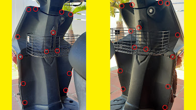
- Remove the top cover and 2 mounting bolts at the front cover.


- Remove 4 screws between the front under the spoiler and the frame.


- Remove front cover and 2 connectors attached.


Step 3: Left and Right Side Cover
- Remove 8 screws located and left, right, and bottom side cover.


- Remove 2 screws at the bottom under the spoiler.

- Then, remove the left and right side cover.


Step 4: Front Under Spoiler and Inner Cover
- Remove 2 screws between front under spoiler and inner cover.


- Remove the front under the spoiler.


- Remove 4 screws at the inner cover and floor panel, then remove the inner cover.


- Remove 4 screws at the bottom under the spoiler.


Step 5: Double Seat and Luggage Box
- Remove 6 screws at the luggage box and a screw front double seat.


- Remove double seat with luggage box.


Step 6: Battery and Center Cover
- For battery removal, please go to my previous POST.
- Remove 2 screws at the bottom center cover and 2 screws at the side center cover.


- Remove center cover.


Step 7: Rear Carrier
- Remove 4 Allen key bolts at the rear carrier.

- Remove rear carrier.

Step 8: Left and Right Cover
- Remove these 2 screws at the tail light.

- Remove 2 screws at the license plate and 2 screws at the rear fender.


- Remove 4 screws at the inner rear fender.


- Remove 2 screws at the inner body cover.


- Pull body cover and remove connectors attached to the body cover.


- Remove seat lock cable.


ASSEMBLE BODY COVERS
Body Covers Assembly or Installation Sequence:

Step 1: Body Covers
- Install body covers in reverse order of removal.
The link tools and components replacement I used in this video are listed below:
Tools/Components/Items (Shopee): 1. Spanner Set 2. Screwdriver Set 3. Allen Key Set Tools/Components/Items (Lazada): 1. Spanner Set 2. Screwdriver Set 3. Allen Key Set Tools/Components/Items (Aliexpress): 1. Spanner Set 2. Screwdriver Set 3. Allen Key Set
Video:
That all from me. If you have any suggestions, please write in the comment section. Thank you for your time 👷.


