Gas sensors play a vital role in various applications, from breathalyzers to industrial gas detection systems. The MQ-3 gas sensor is widely used to detect alcohol vapors, making it ideal for breathalyzer projects and ethanol-based gas detection. In this blog, we will explore how to interface the MQ-3 gas sensor with an Arduino, covering wiring, coding, and real-time monitoring.
 |
| MQ-3 gas sensor with Arduino |
What is the MQ-3 Gas Sensor?
The MQ-3 gas sensor is designed to detect alcohol vapors in the air. It has high sensitivity to ethanol and can be used for applications like breathalyzer systems and alcohol level detection in industrial environments. The sensor provides both analog and digital outputs, making it easy to integrate with Arduino and other microcontrollers.
 |
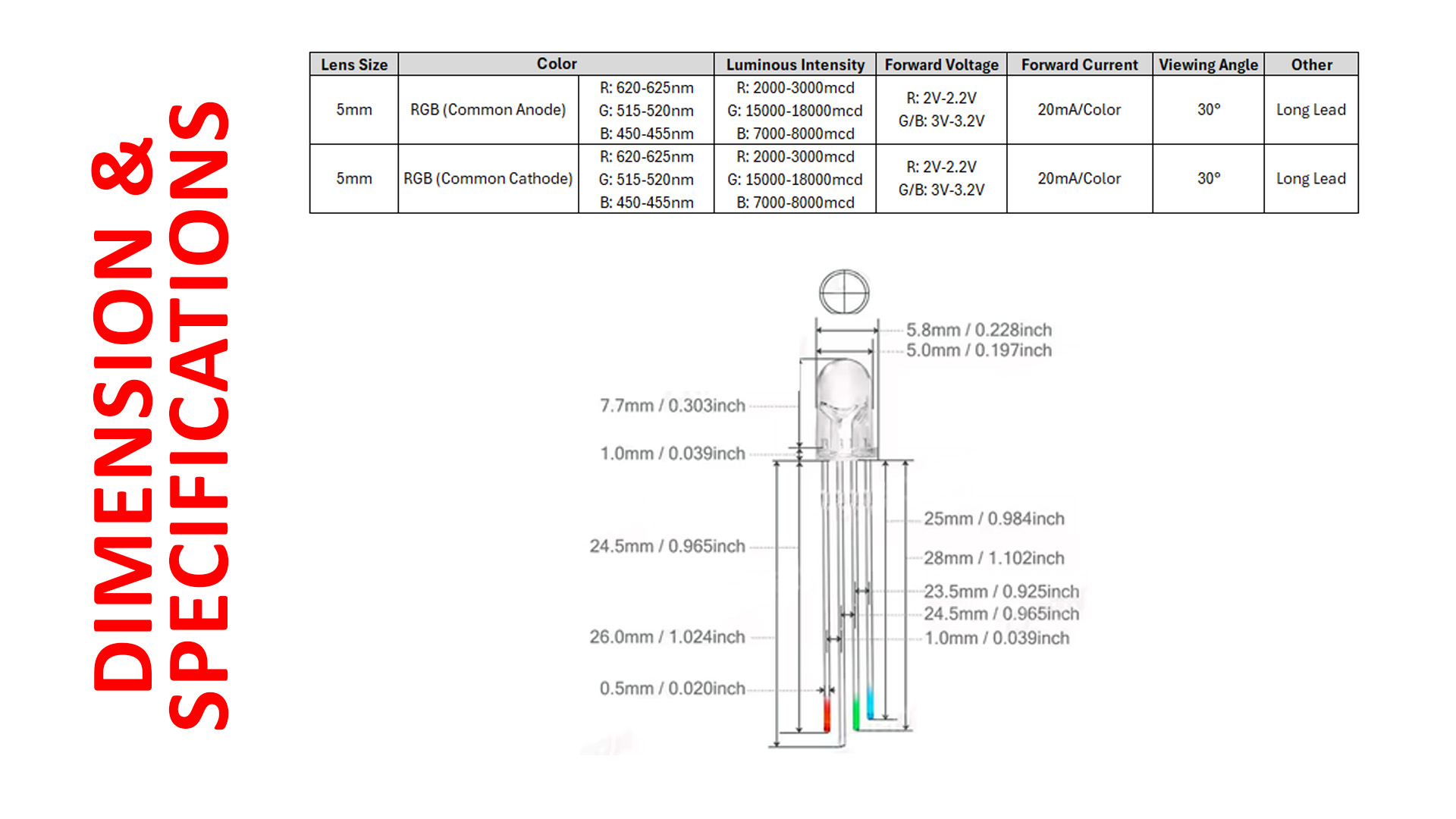
| MQ-3 gas sensor specifications |
Components Required
To get started, you will need the following components:
 |
| Components required for this tutorial |
✅ Arduino UNO board
✅ MQ-3 Gas Sensor Module
✅ Jumper Wires
✅ USB cable for Arduino
Wiring the Components
Follow this simple connection guide:
 |
| Connection MQ-3 gas sensor |
 |
| The connection between the MQ-2 gas sensor and Arduino |
 |
| Wiring diagram |
✅VCC → 5V (Arduino)
✅GND → GND (Arduino)
✅A0 → A0 (Arduino) (for analog readings)
✅D0 (Digital Output, optional) → Any digital pin on Arduino (not used in this example)
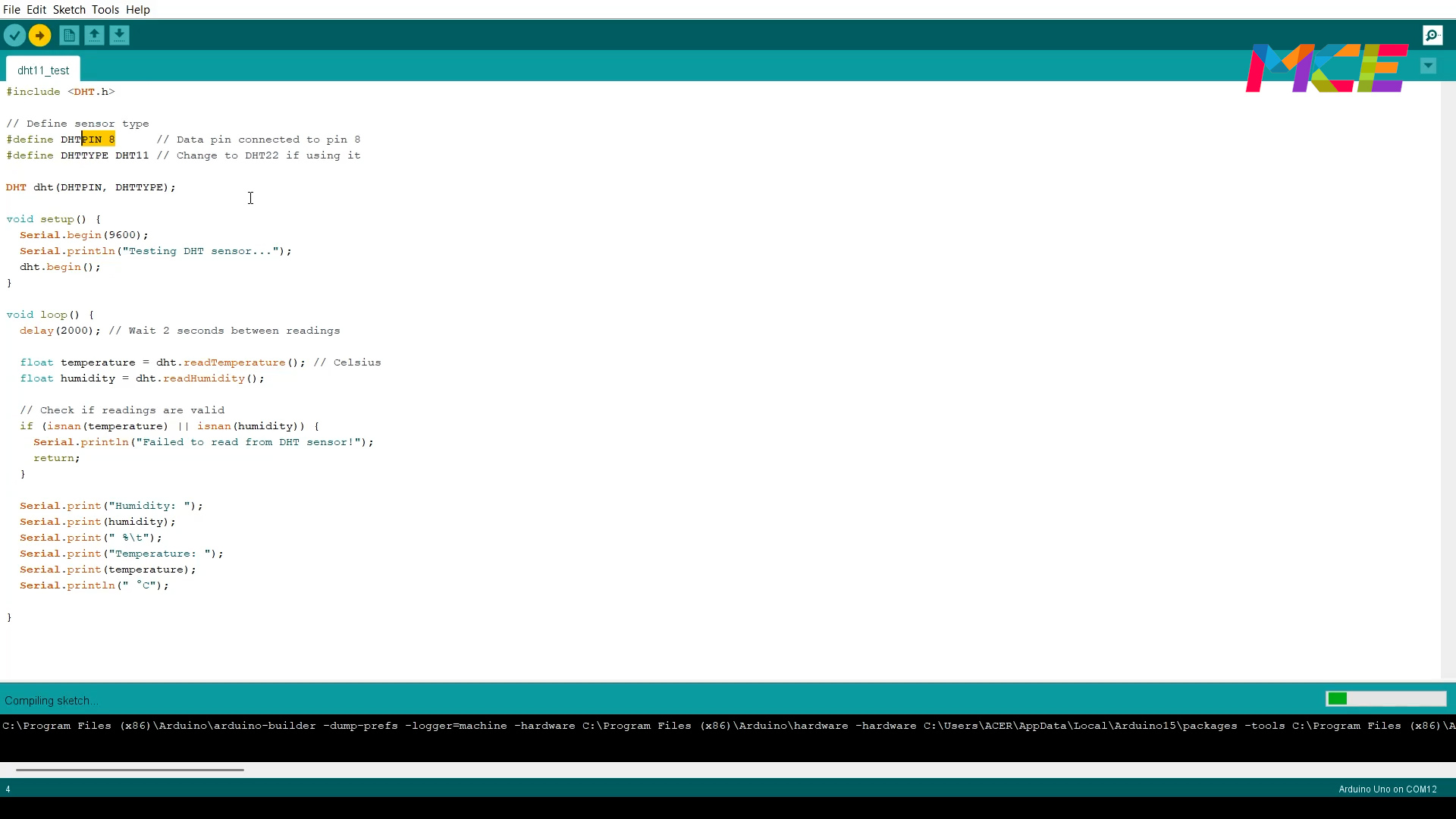
Programming the Arduino
Using the Arduino IDE, upload the following Arduino sketch to read sensor values and display them on the Serial Monitor or you can download the code HERE.
const int sensorPin = A0;  // Analog pin connected to MQ-3
int sensorValue = 0;       // Variable to store sensor readings

void setup() {
  Serial.begin(9600);      // Start serial communication
}

void loop() {
  sensorValue = analogRead(sensorPin); // Read alcohol concentration
  Serial.print("Alcohol Sensor Value: ");
  Serial.println(sensorValue);
  delay(1000); // Wait for a second before next reading
}
 |
| Open Arduino IDE and copy-paste the code |
Testing the Sensor
After uploading the code to your Arduino, open the Serial Monitor in the Arduino IDE.
 | ||
|
 | |
| Introduce a gas source near the sensor and observe the increase in values. |
Conclusion
The MQ-3 gas sensor is a useful component for detecting alcohol vapors in the air, making it ideal for breathalyzer projects and ethanol monitoring. By integrating it with an Arduino, you can build a simple yet effective alcohol detection system. This project is great for learning about gas sensors and how they work in real-world applications.
Tools and components
Shopee:
Lazada:
Aliexpress:
Video
🔔 If you found this guide helpful, share it with fellow makers! For more tutorials, subscribe to our YouTube channel and follow us on social media. 🚀
#arduino #gassensor #mq3 #arduinoprojects #gasdetector